
Multiplexed Biofilm Enrichment
Introduction
The use of an electrochemical multiplexer allows researchers to increase throughput without having to purchase additional potentiostats. Most multiplexers are simple switching devices that allows you to switch a potentiostat between any number of cells for measurements. What most multiplexers can’t do though is apply a potential to that cell when they aren’t the active channel. Gamry Instruments IMX8 Electrochemical Multiplexer does allow you to do this. This key feature lets you apply a potential to a cell without the potentiostat. Each channel within the IMX8 has a local potentiostat that allows you to apply up to +/- 4.9V @ 20 mA. This can be especially useful in slowly changing systems such as biofilm growth.
Upflow anaerobic sludge blanket (UASB) are one of the most common anaerobic digesters (AD). They are used to treat urban wastewater and high strength wastewater with high organic content. 60% of the AD operating are UASB because of their versatility in treating different concentrations of organic content, their small footprint, and low cost of operation. Inside the UASB the granules are composed of several layers of microorganisms. Each layer performs a series of metabolic steps, degrading organic waste and producing methane as a product. Due to the difficulty in studying and profiling the different layers inside the granules, there are still unidentified mechanisms impacting the performance of UASB reactors in relation to intermediate species. The article describes using the 8-channel IMX8 electrochemical multiplexer from Gamry Instruments to grow up to eight biofilms in parallel.
Experimental setup
The media used was 1L of autoclaved media from Ingredion.inc, WA (dCOD 2890 mg/L) was fed to two 300 mL reactors connected in sequence. Each of the two vessels used contained 6 electrodes, each of the two pairs of working electrodes had their counter and reference electrode Ag/AgCl. The working electrode was constructed out of carbon fabric with a size of 4cm x 4cm. The counter electrode was constructed out of carbon felt with the same dimensions as the working electrode. The working and counter electrodes were secured to a titanium wire using 3 nylon screws that is soldered to a 22 AWG wire. The retention time of each reactor pair is 2.5 days, with temperature control set at 32 ˚C and constant nitrogen purging to maintain anaerobic conditions. The inoculation is 20% of the reactor volume of homogenized granules from Ingredion.inc, WA. Each pair of working and counter electrodes had their dedicated reference electrode and a specific polarization potential being applied. Each 300mL vessel had two sets of electrodes, in the first reactor the polarization potential was -700 mV Ag/AgCl and -100 mV Ag/AgCl. The second reactor was polarized at +100 mV Ag/AgCl and +300 mV Ag/AgCl.
Using a Gamry Interface 1010E potentiostat and an IMX8 electrochemical multiplexer, each set of electrodes received a different potential (-700, -100, +100 and +300 mV Ag/AgCl). Inoculation was added at 0.3 days and cyclic voltammetry scans were conducted 30 minutes after inoculation after inoculation.
Results
The goal is to enrich each zone inside anaerobic granules individually in separate reactors. For this first set of reactors there was a potential dependence response observed when polarized at -100 mV, +100 mV and +300 mV (Ag/AgCl) Figure 1. The highest anodic current observed was on the electrode polarized at – 100 mV Ag/AgCl. Due to the fast COD consumption in the first set of reactors (-700mV and -100 mV) the second set showed a 4 μA current increase before going into no-turnover conditions. To test that behavior the flowrate was duplicated on Day 12. After flowrate increase the current on the electrodes polarized at -100 mV and +100 mV and +300 mV (Ag/AgCl) increased to 28, 13 and 15 μA respectively.

Figure 1. Current Generation of the granular sludge over time. The electrode polarized at -700 mV Ag/AgCl did not show a significant current increase regardless of being under the standard reduction potential of the reduction of carbon dioxide to methane. The electrode polarized at -100 mV Ag/AgCl showed the maximum anodic current generated through the experiment with a four-day period of the current consistently being above 0.95 mA. For the electrode with a +100 mV Ag/AgCl potential applied the current stayed under 0.4 mA for the first five days, similar with the lag phase showed by the other enrichments and spiked to 0.6 mA for less than a day. After a total of 12 days the current generated reached a max of 1 mA towards the end of the experiment. The electrode polarized at +300 mV showed a similar behavior to the +100 mV for the first 12 days but reached a maximum current of 1.4 mA.
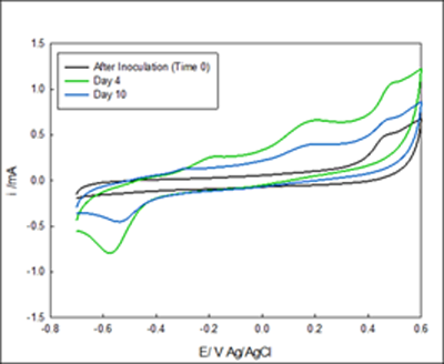
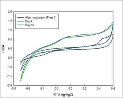
The development of the enriched biofilm was also monitored by cyclic voltammograms. Figure 2- Figure 3. Four voltammograms are shown for each reactor, the fist scan was immediately after inoculation (no biofilm attached to the electrode), after 4 days of enrichment and, after 10 days of enrichment. Figure 3A showed anodic current starting at 0 mV Ag/AgCl, the reduction occurring below -0.4 mV indicates the presence of oxygen in the system despite nitrogen gas purging. Figure 2 B showed anodic current after 2 days, and a diffusion limited region that begins from -100mV Ag/AgCl. After 10 Days of enrichment the anodic current began at -400 mV Ag/AgCl. The voltammograms indicate that anodic current is generated by the anaerobic granules attached on the electrode above -0.3 mV Ag/AgCl. The comparison of the voltammograms at inoculation and after enrichment indicates that anaerobic biofilm has the capability of donating electrons to the electrode surface and that rate of electron exchange can be manipulated with the applied potential.
| A | B |
 |
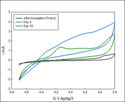 |
Figure 2 Cyclic voltammetry of system #1 The voltammograms A and B are in the same vessel but under different potentials. The media goes from the reservoir into A and out B. A) Voltammogram of biofilm enriched at -700 mV Ag/AgCl. B) Enriched reactor at -100 mV Ag/AgCl.
| A | B |
 |
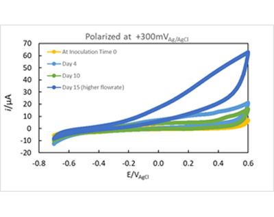 |
Figure 3 Cyclic voltammetry of system #2 The voltammograms A and B are in the same vessel but under different potentials. The media goes from the reservoir into A and out B. A) Voltammogram of biofilm enriched at 100 mV Ag/AgCl. B) Enriched reactor at 300 mV Ag/AgCl
The purpose of this article is to demonstrate how to apply different potentials to each channel of the 8-channel IMX8 multiplexer simultaneously, allowing multiple experiments to be controlled with the same equipment providing the user with the ability to run up to eight sets of electrodes simultaneously.
Want a PDF version of this application note?
Please complete the following form and we will email a link to your inbox!
Categories

