

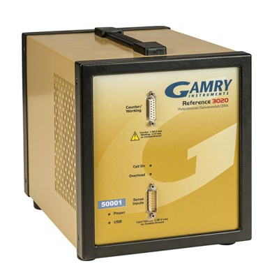
The Reference 3020TM is a high-performance Potentiostat/Galvanostat/ZRA with a maximum current of ±3.0 A (at ±17.5 V compliance) and a maximum voltage of ± 36 V (at ±1.5 A). The Reference 3020 is recommended for battery, electrolyzer, or fuel cell development, as well general electrochemical measurements.
Menu
Close
Potentiostats
Product Details
Overview
The Reference 3020 is a high-current, high-performance USB potentiostat with 11 current ranges from over 3 amps to 300 picoamps and compliance voltage up to 36 volts. With on-board electronics for electrochemical impedance spectroscopy, the Reference 3020 can make measurements over a frequency range from 10 μHz to 3 MHz. The Reference 3020 also has an optional unique feature enabling the measurement of 8 additional voltages. It was developed to be especially useful in applications for Energy Storage and Conversion (ESC) devices.
Applications
- Batteries, Fuel Cells, and Electrolyzers
- Electrocatalysis
- Synthetic Chemistry
- Electroplating Research
- Sensor Development
- Kinetic and Thermodynamic Measurements
- Electrochemical Impedance Spectroscopy
- Corrosion Measurement
- Analytical Electrochemistry
Standard Features
- 2, 3, and 4 Electrode Measurements
- High Voltage Electrometer Mode for Measuring and Applying Potentials Up to 36V
- 3 Control Modes
- Potentiostatic, Galvanostatic and Zero Resistance Ammeter.
- Electrical Isolation
- Floating instrument: use with operating fuel cells, electrolyzers, batteries and autoclaves.
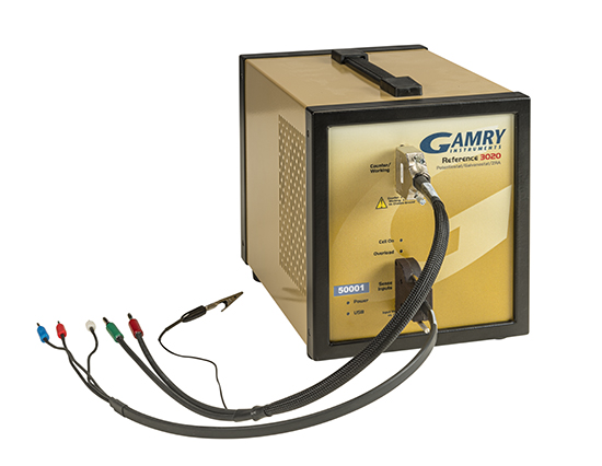
- Separated Voltage and Current Cables
- Always accurate EIS measurements.
- Portable
- Size of two chemistry textbooks, weighing about 5 kgs (11 lbs). Easy USB 2.0 connection to a Windows computer.
- Built-In EIS
- On-board DDS to perform EIS from 10 µHz to 3 MHz (500 kHz maximum on high-compliance)
- DSP (Digital Signal Processing) Mode
- Oversamples for improved signal-to-noise and to ensure accurate capacitance measurements.
- Current Interrupt and Positive Feedback iR Compensation
- Gamry potentiostats and their controlling software use control loop algorithms to accurately measure and correct for uncompensated resistance.
- Auxiliary I/O
- Control additional equipment via additional I/O interfaces: external signal input, analog voltage output, analog current output, auxiliary A/D input, and miscellaneous I/O connector.
- Multichannel Capability
- Up to eight Reference 3020 Potentiostats can be attached and installed on one computer (requires USB hub).
- High Voltage Electrometer
- A special high voltage electrometer allows measurement and potentiostatic control of voltages up to ± 36 volts.
- Fast Setup
- Load the Gamry software, connect the USB cable, and start your experiments.
- Warranty
- Protected by 2-year factory service warranty.
Options
Auxiliary Electrometer
The auxiliary electrometer is a factory installed option that adds an array of eight differential voltage inputs. Each of the eight channels can measure a ± 5 volt signal anywhere over the Reference 3020’s entire compliance voltage range. Impedance measurements up to 100 kHz can also be performed using the auxiliary electrometer.
Extended Cable Lengths
Extended length cell cables (1.5 and 3 meter) are also available for your convenience.
Auxiliary Electrometer Cables: The standard Auxiliary Electrometer cables are 90 cm. Extended length cables (1.5 and 3 meter) are available.
Specifications
SYSTEM |
|
| Potentiostat | Yes |
| Galvanostat | Yes |
| Zero Resistance Ammeter | Yes |
| Floating (Isolated from Earth Ground) | Yes |
| Cell Connections | 2, 3, or 4 |
| Maximum Current | Normal Compliance: ±3 A High Compliance: ±1.5 A |
| Current Ranges | 11 |
| Current Ranges (including internal gain) |
13 |
| Minimum Voltage Resolution | 1 μV |
| Minimum Current Resolution | 1.9 ppm/bit |
| Maximum Applied Potential | ±11 V Normal Compliance: ±36 V High Compliance |
| Rise Time | <250 ns |
| Noise and Ripple | <2 μV rms |
| Minimum Time Base | 3.333 μs |
| Maximum Time Base | 715 s |
| Minimum Potential Step | 12.5 μV |
| Analog/Digital Converter | 20 bit |
| Weight | 6 kg |
| Dimensions | 20 (W) x 23 (H) x 30 (D) cm |
EIS MEASUREMENT |
|
| EIS | 10 μHz - 3 MHz (500 kHz maximum on high compliance) |
| EIS Accuracy | See Accuracy Contour Plot |
| Maximum AC Amplitude | 2110 mV rms |
| Minimum AC Amplitude | 4.03 μV rms |
CONTROL AMPLIFIER |
|
| Compliance Voltage | Normal Compliance: ±17.5 V High Compliance: ±36 V |
| Output Current | >±3 A |
| Speed Settings | 5 |
| Unity Gain Bandwidth | 2150, 1070, 325, 50, 5.2, 0.5 kHz |
ELECTROMETER |
|
| Input Impedance | >1014 Ω |
| Input Current (typical) | <10 pA |
| Bandwidth | >15 MHz at - 3 dB |
| CMRR | >90 dB (DC-100kHz) >70 dB (100kHz-1MHz) |
APPLIED POTENTIAL |
|
| Applied Accuracy | ±0.5 mV ±0.04% of setting |
| Applied Resolution | - |
| Drift | <20 μV/°C |
| Potential Scan Range | ±0.4 V, ±1.6 V, ±6.4 V |
MEASURED POTENTIAL |
|
| Measured Accuracy | ±0.5 mV ±0.04% of reading |
| Measured Resolution | 25 μV, 6.25 μV, 0.625, 0.0625 μV/bit |
| Offset Range | ±10 V |
| A/D Full-Scale Ranges | 12 V, 3 V, 300 mV, 30 mV |
APPLIED CURRENT |
|
| Applied Accuracy |
3 A, 300 mA range - 0.05% of reading (0.015% typ.) 30 mA-3 nA range - 0.04% of reading (0.01% typ.) 300 pA range - 0.1% of reading (0.05% typ.) |
| Applied Resolution | - |
MEASURED CURRENT |
|
| Measured Accuracy |
3 A, 300 mA range - 0.05% of reading (0.015% typ.) 30 mA-3 nA range - 0.04% of reading (0.01% typ.) 300 pA range - 0.1% of reading (0.05% typ.) |
| Measured Resolution | 1.9 ppm/bit |
| Bandwidth (-3 dB) NOTE: Bandwidth is current range dependent |
>10 MHz (3 A-300 μA), >1.5 MHz (30 μA), >0.15 MHz (3 μA) |
| Post Offset Gain | 1, 10, 100 |
| Offset Range | ±1X full-scale |
iR COMPENSATION |
|
| Mode | Current Interrupt and Positive Feedback |
| Minimum Interrupt Time | 33 μs |
| Maximum Interrupt Time | 715 s |
AUXILIARY A/D INPUT |
|
| Range | ±3 V |
| Resolution | 0.1 mV |
| Input Impedance | >100 kΩ or >10 GΩ |
AUXILIARY D/A OUTPUT |
|
| Range | 0-4 V |
| Resolution | 1 mV |