
Measuring Batteries using the Right Setup
Dual-cell CR2032 and 18650 Battery Holder
Introduction
Knowing the exact specifications when testing batteries or any other energy-storage device is crucial. Many parameters affect the capability of a battery, e.g., electrolyte, electrode materials, and temperature. Batteries must pass different tests to check their capacity, voltage window, current rating, internal impedance, leakage current, cycle life, operational temperature range, as well as several impact tests.
In order to get correct, reliable, and reproducible results, researchers must rely on their experimental setup. Wrong setups can affect and falsify measurement results leading to inaccurate conclusions.
The following sections show by means of EIS experiments the influence of the setup on the actual result. Common battery setups (2-terminal) are compared with Gamry’s direct‑contact 4‑terminal battery holders. Shorted lead measurements with dummy cells show the lower limits of Gamry’s battery holders. Two typical setups are compared with Gamry’s battery holders for CR2032 coin cells and cylindrical 18650 batteries. Both holders allow direct‑contact Kelvin sensing.

Figure 1 – Selection of battery connectors for cylindrical batteries and coin cells.
Figure 1 shows typical choices to connect cylindrical batteries and coin cells. Some batteries can be purchased with soldered tabs on each electrode. They allow connecting alligator clips for measurements. If no tabs are available, simple battery holders with two contacts are often used.
All these setups have several drawbacks. Simple battery holders allow only 2‑point configurations, resulting in low precision of measurement. Soldered tabs enable 4‑terminal setups. However, keeping all leads separated while having proper cable alignment and not shorting the battery can be difficult.
Figure 2 presents Gamry’s battery holders for CR2032 coin cells and cylindrical 18650 batteries. Both holders allow direct-contact Kelvin sensing on two batteries (single or in series). Additional resistances from cables or connectors do not falsify the results and allow precise measurements.
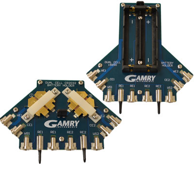
Figure 2 – Gamry’s dual-cell CR2032 (left) and 18650 battery holder (right).
The battery contacts are split up to four separate parts. Current‑carrying and sense leads are completely separated from each other. The setup means that their first direct electrical contact is at the surface of the batteries’ electrodes. In contrast to the setups shown in Figure 1, additional resistances from cables or connectors can be neglected.
All contacts are gold‑plated for high reliability. The printed circuit boards are arranged so that mutual inductance effects and magnetic pickup from the sense leads are minimized.
Potentiostats can be connected using color‑coded banana connectors for stable electrical contacts. All connectors in the assembly are stationary, hence batteries can be changed without disconnecting cables. The physical setup stays the same. This allows reproducible measurements with different cells.
Differences in Experimental Setups
Here we discuss the differences between various experimental setups that are used to perform experiments with batteries.
2‑point configuration
Figure 3 shows a diagram of a 2‑point setup. Working (WE) and working sense (WS) as well as counter (CE) and reference lead (REF) are connected to each other. Typical examples are simple battery holders (see also Figure 1).

Figure 3 – Simplified diagram for a 2 point setup.
In this setup, the sense leads measure the impedance of the cable connector (RWE and RCE) and the connection towards the battery’s electrodes (R+ and R–). Even if the electrical paths to the battery are kept short, the sense leads always measure the impedance from the connections and connectors.
4‑point configuration
Using a 4‑point setup (also called Kelvin connection) may help to decrease the impedance of a measurement setup. In this setup, current‑carrying and sense leads are separated from each other. Figure 4 shows a simplified diagram.

Figure 4 – Simplified diagram for a 4 point setup. For details, see text.
The sense leads should be as near as possible at the battery to decrease additional impedances. However, they will still measure resistances towards the battery (R+ and R-) as they share the same electrical line with the current carrying leads.
A 4 point setup can be realized by using for example soldered tabs on batteries (see Figure 1). However, the whole setup has to be disassembled when changing the battery after finishing a measurement. Complete reproducibility is not given anymore.
Direct contact 4 point configuration
Figure 5 shows a diagram of a direct contact Kelvin connection which is used in Gamry’s battery holders (see also Figure 2).

Figure 5 – Simplified diagram for a direct contact 4 point setup.
In contrast to a conventional 4‑point configuration, current‑carrying and sense leads use four completely separated contacts and electrical lines. Their first direct electrical contact is at the battery’s electrodes. Hence sense leads measure no additional impedances.
Both sense leads as well as both current‑carrying leads are kept close together to reduce mutual inductance errors. As a result, the net magnetic field, which is mainly induced by current‑carrying leads, is minimized. Further, magnetic pickup from the sense leads is reduced by increasing their distance to the current‑carrying pair.
Experiments
Galvanostatic EIS experiments on 18650s and CR2032 lithium‑ion coin cells were performed. Four different setups were used, in the following text also referred to as:
A Direct‑contact 4‑point setup using Gamry’s battery holders
B 4‑point setup using batteries with soldered tabs
C 2‑point setup using batteries with soldered tabs
D 2‑point setup using standard battery holders
Shorted lead
Shorted-lead measurements exhibit the lowest measurable impedance of a system. As the name implies, this test simulates a shorted configuration of cell leads. A metal block with high conductivity is used as dummy cell. Its resistance is in the nW‑range and may be ignored.
Figure 6 shows four magnitude‑only Bode plots of shorted-lead experiments with Gamry’s battery holders. The spectra were recorded from 100 kHz to 10 mHz. The AC amplitude is 1 A. A standard 60 cm cable and a low‑Z cable (part # 990-00239) were used.

The impedance spectrum may be separated into two parts. At higher frequencies, the impedance is limited by inductance. This portion is represented by a diagonal line, mainly affected by the cables. Separating current‑carrying and sense leads while twisting the cable pairs can help to reduce mutual inductive effects.
At frequencies below 100 Hz, the system is limited by the lowest measurable impedance. This section is represented by a horizontal line. Impedances below this value cannot be measured. This part is dominated by the potentiostat and the experimental setup, i.e., impedance of cables and connectors.
A shorted-lead spectrum can be modeled by a resistor in series with an inductor (RL‑model). Table 1 displays the results for both battery holders and their direct‑contact Kelvin connections.
|
|
|
|
||
|
|
|
|
|
|
|
|
|
|
|
|
|
|
|
|
For more information about low impedance measurements and shorted lead tests, see also the application note section on Gamry’s website: www.gamry.com |
EIS on cylindrical 18650s and CR2032 coin cells
Figure 7 and Figure 8 show several Nyquist diagrams of commercially available 18650 lithium‑ion batteries and CR2032 coin cells.

Figure 7 – Nyquist diagrams of an 18650 battery with different experimental setups.![]()
For details, see text.

All spectra were recorded from 100 kHz to 10 mHz. The AC amplitude was 100 mArms for the 18650 battery and 10 mArms for the coin cell. Before each measurement, both batteries were potentiostatically held at 3.6 V (18650 battery) and 4.0 V (CR2032 coin cell) for at least one hour to ensure a constant potential. The same batteries are used for each measurement.
In addition, both shorted-lead spectra of Gamry’s battery holders are shown which are discussed in the previous section (see also Figure 6).
As current‑carrying and sense leads are completely separated at the direct‑contact 4‑point setup, no additional impedances are measured. The shorted-lead spectra of both battery holders are only a short line in the low µW‑range. They have nearly no effect on the results compared to the batteries’ impedances in the mW‑range.
All other spectra are shifted to higher resistances (Zreal) caused by additionally measured impedances from cables and connectors. Even though cable-pairs are twisted, and both sense leads are kept as close as possible to the battery, additional resistances of several mW are measured.
This affects—among other things—the value of the equivalent series resistance (ESR). The ESR is the sum of resistances of electrodes, electrolyte, and electrical contacts. ESR affects the performance of a battery, hence it is a crucial parameter for developing energy-storage devices.
Table 2 lists ESR‑values for all setups shown in Figure 7 and Figure 8, including their percentage deviations.
|
|
Cylindrical 18650 |
CR2032 coin cell |
||
|
Setup |
ESR |
Deviation |
ESR |
Deviation |
|
A |
71.0 |
- |
345.1 |
- |
|
B |
73.6 |
3.7 |
435.2 |
26.1 |
|
C |
78.2 |
10.1 |
441.6 |
28.0 |
|
D |
164.8 |
132.1 |
555.8 |
61.1 |
Table 2. ESR results using the two different battery holders and four different setups (see text for details).
In both cases, the direct‑contact 4‑point setup (A) exhibits lower ESR‑values. Compared to the standard Kelvin connection (setup B), deviations vary between 3.7% and more than 26%. These deviations account for nearly 3 mW for the 18650 cell and more than 90 mW for the coin cell.
Additionally measured impedances from connectors drastically falsify the results in both 2‑point setups (C and D). Deviations of measured ESR‑values can be more than 100% and hundreds of mW.
| NOTE: A correct experimental setup is even more crucial when measuring low‑impedance devices in the low‑mW or µW‑range. |
Reproducibility
A second important issue when measuring batteries is the reproducibility of the results. To improve capabilities of batteries, many different compositions of electrolytes and electrode materials must be tested. Results are often just subtly different, which makes narrowing down the choice of possible candidates for further tests even more difficult. Hence measurement results have to be precise and reproducible.
Figure 9 shows 32 single‑frequency EIS experiments using two different experimental setups. One 18650 battery was alternately measured using either a standard 4‑point setup or Gamry’s 18650 holder with its direct‑contact 4‑point setup. The frequency was set to 1 kHz and the impedance was measured for 150 s.

Reproducibility is much higher when using Gamry’s 18650 holder (blue curves). The measured impedances are nearly equal. Reassembling of the setup does not affect the results as the setup stays unaffected.
In contrast, standard Kelvin sensing (red curves) shows a wide distribution in the impedance between 70 mW and 75 mW. The results are greatly influenced by the physical setup, which always changes slightly when dis‑ and reconnecting battery and cables.
Table 3 lists average impedances and deviations for each setup resulting from all single‑frequency experiments.
| Standard 4‑point |
Direct‑contact 4‑point |
| 71.20 ± 1.27 mΩ (±1.79 %) |
68.20 ± 0.04 mΩ (±0.05 %) |
Table 3. Comparison of reproducibility with standard versus direct-contact battery holders.
The conventional 4‑point setup shows in general higher impedance values than the direct‑contact 4‑point setup. The percentage deviation is about 4.4%.
Summary
This application note addresses research on energy-storage devices. Gamry’s dual-cell battery holders for CR2032 coin cells and cylindrical 18650 batteries are introduced. These allow direct‑contact Kelvin sensing for more precise and reproducible results.
When testing different electrolytes, electrode materials, or whole cells, even slight variations in the results can lead to wrong assumptions. Correct cable alignment and stable electrode connections are required. This fact is even more crucial when measuring low‑impedance cells in the sub‑mΩ or even µΩ‑range.
For that reason, both battery holders are designed with four completely separated contacts and electrical lines for sense and current‑carrying leads. Additional impedances due to connectors can be ignored. The compact setup minimizes mutual inductive effects and magnetic pickup in the sense leads.
For this application note, shorted-lead experiments were performed, which exhibit the lowest measurable impedance of Gamry’s battery holders.
In addition, galvanostatic EIS experiments with commercially available lithium‑ion batteries show the influence of the experimental setup on measurement results. Gamry’s direct‑contact 4‑point setup is compared to standard 2‑point and 4‑point setups. The experiments show that wrong setups can drastically falsify measurement results. Gamry’s direct‑contact Kelvin connection allows measuring lowest impedances without any additional resistances.
Finally, single‑frequency EIS measurements were performed comparing two different setups: direct‑contact 4‑point vs. standard 4‑point. The results show the high reproducibility of Gamry’s battery holders and necessity of a stable experimental setup.
Want a PDF version of this application note?
Please complete the following form and we will email a link to your inbox!
Categories

